What Are Transformer Accessories and Auxiliary Materials?
Transformer accessories and auxiliary materials are the components and insulating substances that support, protect, and optimize the performance of power transformers and motors. Without reliable accessories, even a well-engineered transformer core will fail prematurely — insulation breakdown accounts for approximately 70% of transformer failures in service. Understanding what these materials are, how they function, and how to select them correctly is essential for electrical engineers, procurement specialists, and energy infrastructure operators alike.
This article covers the core categories of transformer accessories and auxiliary materials, their functional roles, key selection criteria, and practical application guidance — with a focus on special interlayer insulating materials, which represent one of the most technically demanding areas within this product family.
The Functional Scope of Transformer Auxiliary Materials
Transformer auxiliary materials serve three primary functions: electrical insulation between conductive components, mechanical support to prevent winding displacement under load, and thermal management to dissipate heat generated during operation. A high-performance transformer relies on these materials working together as a system — not as isolated components. Typical auxiliary material categories include interlayer insulating sheets, pressboard, transformer kraft paper, fiberglass-reinforced laminates, and supporting structural components.
Why Insulating Materials Are the Critical Variable
Among all auxiliary materials used in transformer manufacturing, insulating materials are widely regarded as the most critical because they directly influence the transformer’s dielectric strength, thermal stability, operational reliability, and overall service life. While structural components provide mechanical support and conductive materials enable energy transfer, the insulation system is ultimately responsible for maintaining electrical separation between energized parts and preventing catastrophic failure under continuous operating stress.
A transformer’s insulation system must withstand a complex combination of electrical, thermal, mechanical, and environmental stresses throughout decades of operation. During normal service, insulating materials are continuously exposed to high voltages, localized electric field concentrations, elevated operating temperatures, moisture ingress, oxidation, and occasional overload conditions. Over time, these stresses gradually degrade the insulation structure, reducing dielectric performance and increasing the likelihood of partial discharge, short circuits, and insulation breakdown. For this reason, the quality and stability of insulating materials are often considered the primary determinants of transformer longevity.
Industry studies indicate that the average operational lifespan of a distribution transformer typically ranges from 25 to 40 years. However, this lifespan can vary significantly depending on the quality of the insulation system, manufacturing standards, operating environment, and maintenance practices. Transformers equipped with high-performance insulation materials and properly maintained cooling systems can remain in reliable service for several decades with minimal degradation. In contrast, units manufactured with lower-grade insulation materials frequently experience accelerated aging, reduced dielectric margins, and substantially higher failure rates. Some industry assessments suggest that transformers using substandard insulation systems may exhibit failure rates up to three times higher within the first ten years of operation compared with units utilizing premium-grade insulating materials.
The importance of insulation quality becomes even more evident in modern power systems, where transformers are increasingly subjected to fluctuating loads, harmonic distortion, higher ambient temperatures, and demanding grid conditions associated with renewable energy integration. Under these circumstances, inferior insulating materials may suffer from faster thermal aging, resin cracking, moisture absorption, or reduced mechanical strength, all of which can compromise transformer safety and reliability. Even relatively small defects in insulation performance can eventually lead to expensive outages, unplanned maintenance, or complete equipment replacement.
Consequently, material selection should never be treated as a purely cost-driven procurement decision. Instead, it represents a long-term strategic investment in equipment reliability, operational safety, and lifecycle cost reduction. High-quality insulating materials may increase initial manufacturing costs, but they often deliver substantial economic benefits through extended service life, reduced maintenance frequency, lower risk of unexpected failures, and improved system stability. This is particularly important for utilities, industrial facilities, and renewable energy infrastructure operators, where transformer downtime can result in significant operational and financial losses.
As a result, leading transformer manufacturers place strong emphasis on the selection, testing, and qualification of insulating materials. Comprehensive quality-control procedures, accelerated aging tests, thermal endurance evaluations, and dielectric performance verification are increasingly integrated into modern manufacturing processes to ensure that insulation systems meet strict international reliability standards. In today’s power industry, insulation is no longer viewed as a secondary supporting material — it is recognized as one of the core technologies that determines the long-term performance and resilience of the entire transformer system.
Core Categories of Transformer Accessories
Transformer accessories span both external fittings and internal insulating components. Each category plays a specific role in system integrity and performance. The table below summarizes the primary accessory categories, their functions, and the materials typically involved.
Table 1: Main categories of transformer accessories and their functional roles
Category
Primary Function
Typical Materials
Application Location
Interlayer Insulating Sheets
Electrical isolation between winding layers
DMD, NMN, fiberglass laminates
Between winding layers
Transformer Pressboard
Structural support and oil-impregnated insulation
Cellulose-based pressboard
Core clamping, barriers
Transformer Kraft Paper
Conductor wrapping insulation
Sulfate cellulose pulp
Conductor surfaces
Fiberglass Laminates (FR4 / G10)
High-strength structural insulation
Epoxy-bonded fiberglass
Coil supports, spacers
Cooling & Oil Accessories
Heat dissipation, oil circulation
Metal, seals, gaskets
Tank exterior, conservator
Tap Changer Components
Voltage regulation under load
Contact alloys, insulating rods
Voltage regulation zone
Interlayer Insulating Materials: The Most Technically Demanding Category
Special interlayer insulating materials for power transformers and motors are designed to withstand continuous high-voltage stress while maintaining dimensional stability across a wide temperature range. The most commonly used types include:
DMD (Polyester Film / Polyester Fiber Composite): A three-layer structure combining polyester film with non-woven fabric on both sides. DMD offers excellent dielectric strength (typically 10–25 kV/mm), good tear resistance, and is widely used in dry-type distribution transformers. Standard thicknesses range from 0.15mm to 0.5mm.
NMN (Nomex / Mylar / Nomex): A premium composite combining aramid paper (Nomex) with polyester film. NMN is rated for continuous operating temperatures up to 220°C, making it ideal for Class H insulation systems in high-stress motors and traction transformers.
Fish Paper (Vulcanized Fiber): A traditional material offering good mechanical toughness and moderate dielectric performance. Still used in legacy equipment servicing and lower-voltage applications.
Fiberglass Reinforced Laminates: Used where mechanical rigidity is prioritized alongside insulation. Epoxy-bonded fiberglass sheets (such as FR4 or G11) offer compressive strength exceeding 350 MPa and are used as coil spacers and structural supports inside winding assemblies.
External Accessories: Conservators, Bushings, and Protection Devices
External transformer accessories protect the internal environment and ensure operational safety. Oil conservators maintain stable oil pressure by accommodating thermal expansion of insulating oil. Buchholz relays detect gas accumulation from internal faults — a critical early-warning mechanism that can prevent catastrophic failures. Bushings provide safe high-voltage conductor entry points through the transformer tank while maintaining electrical separation from the grounded tank body. Silicone rubber bushings have increasingly replaced porcelain types due to better hydrophobicity in outdoor installations.
Special Insulating Materials for Power Transformers and Motors
The insulation system of a transformer is not a single material but a carefully engineered assembly. Each component must be compatible with the others — chemically, thermally, and electrically — across decades of operational service. A mismatched insulating material introduced during manufacturing or maintenance can shorten transformer life by 30–50%, even if every other component meets specification.
Thermal Classification and Material Selection
IEC and NEMA standards define insulation thermal classes that directly govern material selection. Choosing a material rated below the operating temperature class of the transformer is a common and costly error. The table below outlines the main insulation classes and typical material assignments:
Table 2: Insulation thermal classes and corresponding material options for transformer winding insulation
Insulation Class
Max. Continuous Temp.
Typical Materials
Typical Applications
Class A
105°C
Cotton, silk, paper, oil-impregnated cellulose
Oil-filled distribution transformers
Class E
120°C
Polyester enamels, some laminates
Small motors, low-voltage equipment
Class B
130°C
DMD, mica, fiberglass laminates
Dry-type distribution transformers
Class F
155°C
Modified polyester, silicone composites
Industrial motors, traction equipment
Class H
180°C
NMN, aramid laminates, silicone rubber
High-load motors, traction transformers
Class C
220°C+
Mica, ceramic, polyimide films
Power electronics, extreme-duty applications
Key Performance Metrics for Insulating Materials
When evaluating insulating materials for transformer and motor applications, engineers should assess the following performance parameters as standard practice:
Dielectric strength (kV/mm): The maximum electric field the material can withstand without breakdown. High-quality DMD typically achieves 15–25 kV/mm.
Volume resistivity (Ω·cm): Measures leakage current resistance. Values above 10¹³ Ω·cm are standard for winding insulation materials.
Tensile strength (MPa): Critical for materials that experience mechanical stress during winding and operation. Fiberglass laminates typically exceed 200 MPa in tensile strength.
Thermal endurance (hours at rated temperature): Per IEC 60216, materials are tested at sustained elevated temperatures to extrapolate expected service life — often targeting 20,000 hours at rated class temperature.
Oil compatibility: For oil-filled transformers, insulation materials must be chemically compatible with mineral oil or ester fluids without degrading or releasing contaminants over time.
Dimensional stability: Shrinkage or expansion at operating temperature can create gaps that reduce dielectric performance or introduce mechanical stress on conductors.
Dielectric Strength by Insulating Material (kV/mm)
Polyimide Film
~280 kV/mm
NMN Composite
~18–22 kV/mm
DMD Composite
~15–20 kV/mm
FR4 Fiberglass
~14–18 kV/mm
Transformer Pressboard
~8–12 kV/mm
Values are indicative ranges based on standard testing conditions; actual performance depends on thickness, moisture content, and manufacturing process.
How to Select Transformer Insulating Materials: A Practical Framework
Selecting the right insulating material for a transformer or motor application requires balancing electrical requirements, thermal class, mechanical constraints, and environmental conditions. Using a structured selection framework reduces the risk of specification errors and premature failures in the field.
Step 1 — Define the Thermal Operating Environment
Begin with the maximum continuous winding temperature of the equipment. This is typically provided in the transformer nameplate data or equipment specification sheet. Add a safety margin of at least 10–15°C above the rated hot-spot temperature when selecting insulation class. For example, a transformer with a rated hot-spot temperature of 140°C should use Class F or Class H insulation materials to ensure adequate thermal life margin.
Step 2 — Assess Voltage Stress Requirements
Calculate the maximum voltage gradient across each insulation layer based on winding voltage distribution. For medium-voltage dry-type transformers (typically 6 kV to 36 kV), interlayer insulation must sustain impulse voltages of 60–200 kV without breakdown. A dielectric safety factor of 2× to 3× the steady-state operating voltage is commonly applied as a design minimum. This determines the required material thickness and dielectric strength rating.
Step 3 — Consider Mechanical and Processing Requirements
Winding processes exert tensile and compressive forces on insulating materials. Materials that are too rigid may crack during winding; materials that are too compliant may deform under winding tension and create uneven insulation distribution. The ideal material for high-speed automated winding processes combines sufficient flexibility to conform to conductor geometries with adequate stiffness to maintain layer uniformity. Thickness tolerance — typically ±5% or better — is an important manufacturing quality criterion that directly affects layer-to-layer uniformity in the finished winding.
Step 4 — Verify Environmental and Compliance Factors
For transformers deployed in humid, coastal, or chemical environments, the moisture absorption characteristics of insulating materials are critical. Cellulose-based materials are inherently hygroscopic and require careful drying and vacuum-oil impregnation processes to maintain their insulating properties. Synthetic materials such as polyester-based DMD or aramid composites absorb significantly less moisture, making them preferable for dry-type transformers in challenging environments. Additionally, compliance with standards such as IEC 60641 (pressboard), IEC 60819 (non-cellulosic sheet materials), and UL 94 flame retardancy ratings should be confirmed for each material in the insulation system.
Relative Failure Risk vs. Insulation Material Grade (Illustrative Trend)
Higher-grade insulating materials correlate with progressively lower transformer failure risk over service life. Illustrative model based on industry maintenance data.
Composite Reinforcing Materials: GFRP and Fiber Bar Mesh Applications
Beyond traditional insulating materials, composite reinforcing materials — particularly glass fiber reinforced polymer (GFRP) components — play a growing role in the transformer and motor manufacturing ecosystem. GFRP components offer a unique combination of high mechanical strength, electrical non-conductivity, and corrosion resistance that conventional metal structural components cannot match in certain applications.
GFRP Components in Transformer Construction
In dry-type and cast-resin transformers, GFRP structural components replace steel in locations where magnetic field induction in metallic parts would cause eddy current losses or create unwanted conductive paths. Typical GFRP applications include:
Winding coil spacers and support blocks: Maintaining precise inter-winding distances and preventing conductor displacement under electromagnetic force.
Core clamping rods and tie rods: GFRP tie rods clamp the core lamination stack without introducing a conductive loop that would generate circulating currents. This is a critical function in large power transformers where core losses must be minimized.
Tap changer insulating shafts: Providing mechanical actuation of tap changer contacts while maintaining electrical isolation between operating positions.
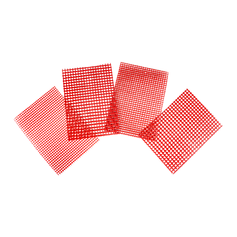
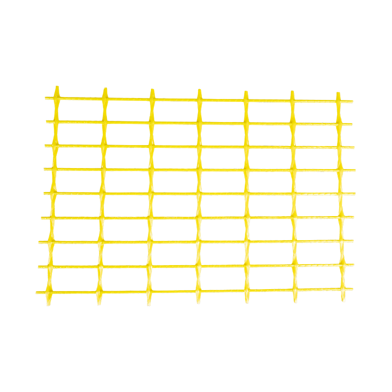
Fiber bar mesh sheets (GFRP mesh): Used as reinforcement within cast-resin windings, replacing conventional steel mesh to avoid eddy current generation while providing structural reinforcement against thermal and mechanical shock.
Advantages of GFRP Over Conventional Materials in Electrical Equipment
The adoption of GFRP in transformer and motor manufacturing has expanded significantly over the past two decades, driven by performance advantages over both metals and traditional glass-epoxy laminates in certain roles. Key advantages include:
High tensile strength-to-weight ratio: GFRP fiber bars typically achieve tensile strength of 800–1200 MPa at roughly one-quarter the weight of equivalent steel sections.
Zero magnetic permeability: Unlike steel, GFRP does not interact with transformer magnetic fields, eliminating eddy current losses in structural components.
Corrosion immunity: In coastal or chemically aggressive environments, GFRP structural components maintain their mechanical properties without degradation, extending maintenance intervals.
Dimensional stability: Low coefficient of thermal expansion ensures that GFRP spacers and support structures maintain their dimensions across the full operating temperature range, preventing loosening of winding assemblies over time.
Production Equipment for GFRP Components
The quality and long-term reliability of GFRP components are closely linked to the sophistication of the production equipment used during manufacturing. Advanced automated pultrusion lines for fiberglass reinforced bars, together with high-precision filament winding systems for hollow tubes and structural cylinders, enable manufacturers to achieve highly consistent dimensional accuracy, stable wall thickness, and optimized fiber alignment. These factors are critical because even minor variations in fiber distribution or resin content can significantly influence the mechanical strength, dielectric properties, and thermal stability of the final product.
Modern production facilities increasingly rely on intelligent manufacturing systems equipped with real-time monitoring and closed-loop control technologies. Sensors installed throughout the production line continuously track key process parameters such as resin impregnation quality, fiber tension, winding angle, curing temperature, and pulling speed. By analyzing this data in real time, manufacturers can immediately detect process deviations, minimize void formation, prevent dry fiber defects, and maintain a uniform fiber volume fraction across the entire component. This level of automation not only improves product consistency, but also greatly reduces scrap rates and enhances overall production efficiency.
In addition, precision-controlled curing systems ensure that the resin matrix achieves complete and uniform polymerization, which is essential for maintaining both mechanical integrity and electrical insulation performance under demanding operating conditions. Automated data logging and traceability functions further allow each production batch to be fully documented, including raw material records, processing conditions, inspection results, and quality verification data. Such traceability is increasingly required in industries with strict reliability standards, particularly in the manufacture of high-voltage power transformers, switchgear systems, and other critical electrical infrastructure applications.
For components used in high-voltage transformer environments, consistency is especially important because the materials are often exposed to continuous electrical stress, elevated temperatures, vibration, and long service lifetimes. Any internal defect, dimensional inconsistency, or variation in curing quality can potentially compromise insulation performance or mechanical stability. Therefore, manufacturers that invest in state-of-the-art automated equipment and intelligent quality-control systems are generally better positioned to deliver GFRP components with superior reliability, repeatability, and compliance with international industry standards.
Quality Standards, Testing, and Procurement Considerations
Specifying and procuring transformer accessories and auxiliary materials without attention to quality standards is one of the most common sources of field failures. A material that passes visual inspection but has not been tested to the relevant IEC or ASTM standard may still fail under actual service conditions within months. The following standards framework should guide procurement decisions:
Relevant International Standards
IEC 60641: Pressboard and presspaper for use in electrical equipment — covers dimensional, mechanical, and electrical property requirements.
IEC 60819: Non-cellulosic paper and paperboard for electrical purposes — applicable to synthetic insulating sheet materials including polyester-based composites.
IEC 60216: Thermal endurance evaluation of electrical insulating materials — defines test methods for correlating accelerated aging data with expected service life.
ASTM D149: Standard test method for dielectric breakdown voltage and dielectric strength of solid electrical insulating materials.
IEC 61212: Insulating materials — industrial rigid laminated tubular and solid electrical insulating materials based on thermosetting resins for use in electrical equipment.
UL 94: Flammability testing of plastic materials for parts in devices and appliances — V-0 rating is typically required for materials in proximity to live conductors.
Key Supplier Qualification Criteria
When qualifying suppliers of transformer insulating materials and accessories, procurement teams should evaluate the following criteria systematically:
ISO 9001 quality management system certification — confirms documented process control and traceability
In-house testing laboratory capability — third-party reliance introduces lead time and limits real-time quality feedback during production
Material certificate of compliance (CoC) and batch traceability records provided with each shipment
Production capacity and lead time consistency — critical for transformer OEMs with scheduled production programs
Technical support capability — suppliers with R&D teams can assist with material selection optimization for non-standard applications
Export experience and compliance with destination market regulatory requirements (CE, UL, RoHS where applicable)
Common Quality Failures and How to Avoid Them
Field experience consistently points to several recurring quality failure modes in transformer insulating materials. Being aware of these failure modes allows procurement and engineering teams to build targeted incoming inspection criteria:
Moisture contamination at delivery: Cellulosic materials are particularly vulnerable. Require humidity-controlled packaging and check moisture content on receipt (target <0.5% for pressboard going into oil-filled transformers).
Thickness non-uniformity: Variance beyond ±5% in interlayer insulation thickness creates weak spots where dielectric stress concentrates. Measure at multiple points across each sheet.
Delamination in composite materials: DMD and NMN composites that have been incorrectly stored or handled may show edge delamination. Inspect edges visually and perform a simple peel test on sample pieces from each batch.
Incorrect material substitution: Receiving Class B material when Class H was specified is not always detectable by visual inspection alone. Always verify thermal class marking and request test certificates tied to the specific production batch.
About Zhejiang Yuanda Fiberglass Mesh Co., Ltd.
Zhejiang Yuanda Fiberglass Mesh Co., Ltd. was founded in 2000. It is a technology-oriented manufacturing enterprise focusing on the new materials field, specializing in the research and development, and production of composite reinforcing materials, insulating materials, and related intelligent equipment. Committed to providing professional and reliable products and services to customers worldwide, the company is located in the Yangtze River Delta Economic Circle of China, in close proximity to Ningbo Port and Shanghai Port — a geographical advantage that has greatly facilitated its import and export operations globally.
The company covers an area of nearly 33,000 square meters with modern standard workshops equipped for precision manufacturing. Over 25 years of focused engagement in the new materials field has established Yuanda as a trusted supplier to transformer and motor manufacturers across multiple continents.
The company's operations are organized around three core business segments:
Composite material fiber bars and fiber bar mesh sheets (GFRP), as well as supporting production equipment — serving transformer OEMs and infrastructure construction markets requiring non-conductive, high-strength structural reinforcement.
Special interlayer insulating materials for power transformers and motors — including DMD, NMN, and fiberglass laminate products engineered to meet the thermal, electrical, and mechanical demands of modern electrical equipment.
Continuous innovation and industrial collaboration — deepening technological capabilities and expanding product application scope across the new materials sector, with a strategic focus on becoming a leading domestic supplier of composite new materials in China and a trusted global partner.
For the past 25 years, Zhejiang Yuanda has deepened technological innovation and industrial collaboration, continuously expanding the application scope of its products and earning wide recognition from customers in China and internationally. The company's commitment is to inject continuous impetus into the high-quality development of the composite new materials industry.
Frequently Asked Questions
Q1: What is the difference between DMD and NMN insulating materials?
DMD is a three-layer composite of polyester film sandwiched between polyester non-woven fabric layers, rated for Class B/F applications (up to 155°C). NMN replaces the outer fabric layers with aramid paper (Nomex), achieving Class H thermal performance (up to 180°C) with superior mechanical toughness. NMN is used when higher thermal endurance is required; DMD is the cost-effective choice for standard dry-type distribution transformer applications.
Q2: How do I know what insulation class my transformer requires?
The required insulation class is determined by the transformer's rated hot-spot winding temperature, which is specified on the nameplate or in the equipment datasheet. Cross-reference this temperature with the IEC insulation class table (A, E, B, F, H, C). When in doubt, apply at least one class above the rated temperature to ensure adequate thermal life margin — for example, using Class H materials in a Class F application extends expected insulation life significantly.
Q3: Can GFRP components replace steel in all transformer structural applications?
GFRP is well suited to replace steel in locations where electrical non-conductivity is important — core clamping rods, inter-winding spacers, and insulating shafts are typical examples. However, GFRP is not suitable for parts requiring high ductility or where welding is necessary. The tank body, cooling fins, and current-carrying structural parts remain in steel. The choice to use GFRP should be based on functional requirements at each specific location within the equipment design.
Q4: What storage conditions are required for transformer insulating materials?
Cellulosic materials (pressboard, kraft paper) must be stored in a dry, temperature-controlled environment at relative humidity below 50% to prevent moisture absorption. Synthetic composites such as DMD and NMN are less hygroscopic but should still be stored sealed in their original packaging away from UV exposure and chemical fumes. All insulating materials should be stored horizontally or supported to prevent deformation, and should be used within the manufacturer's recommended shelf life — typically 2–5 years depending on material type.
Q5: How do interlayer insulating materials affect transformer efficiency?
Interlayer insulation influences transformer efficiency primarily through its effect on winding geometry and thermal management. Materials with better dimensional consistency and lower thickness allow tighter winding designs that reduce the mean turn length and therefore copper losses. Additionally, materials with good thermal conductivity help dissipate heat from the hottest winding sections, reducing hot-spot temperatures and the associated increase in winding resistance — both of which contribute to lower no-load and load losses in well-designed transformers.
Q6: What certifications should I look for when sourcing transformer accessory materials?
At a minimum, verify that the supplier holds ISO 9001 certification and that the materials are tested to the applicable IEC or ASTM standards for their product category. For materials entering specific markets, additional compliance may be required: CE marking for Europe, UL listing for North America, and RoHS compliance for restriction of hazardous substances. Request batch-specific test certificates — not just product-level approvals — to confirm that the actual material received meets the specifications on which the approval was granted.
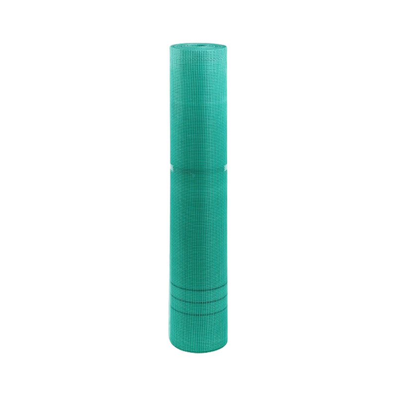
Epoxy Glass Fiber Mesh Cloth is a reinforcing material made from a square-hole mesh fabric woven from alkali-free glass fiber yarn and polyester filaments. After high-temperature dehydration, it is im...
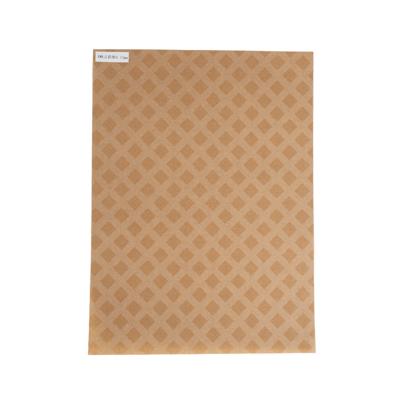
Diamond Dot-painted Insulating Paper (DDP) is a double-sided diamond-patterned insulating material made by coating a composite epoxy resin adhesive in a diamond-shaped dot pattern onto an electrical i...
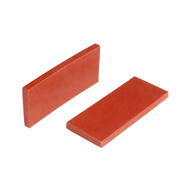
Transformer-specific insulating mats are sheet-like insulating components made from alkali-free electrical fiberglass cloth impregnated with epoxy resin, baked, and hot-pressed under high temperature ...
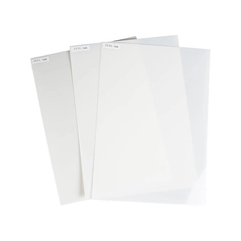
I. Product IntroductionThe composite shroud for dry-type transformer coils is made of special insulating materials. The core consists of a polyester film (or PET film) coated with a special heat-resis...
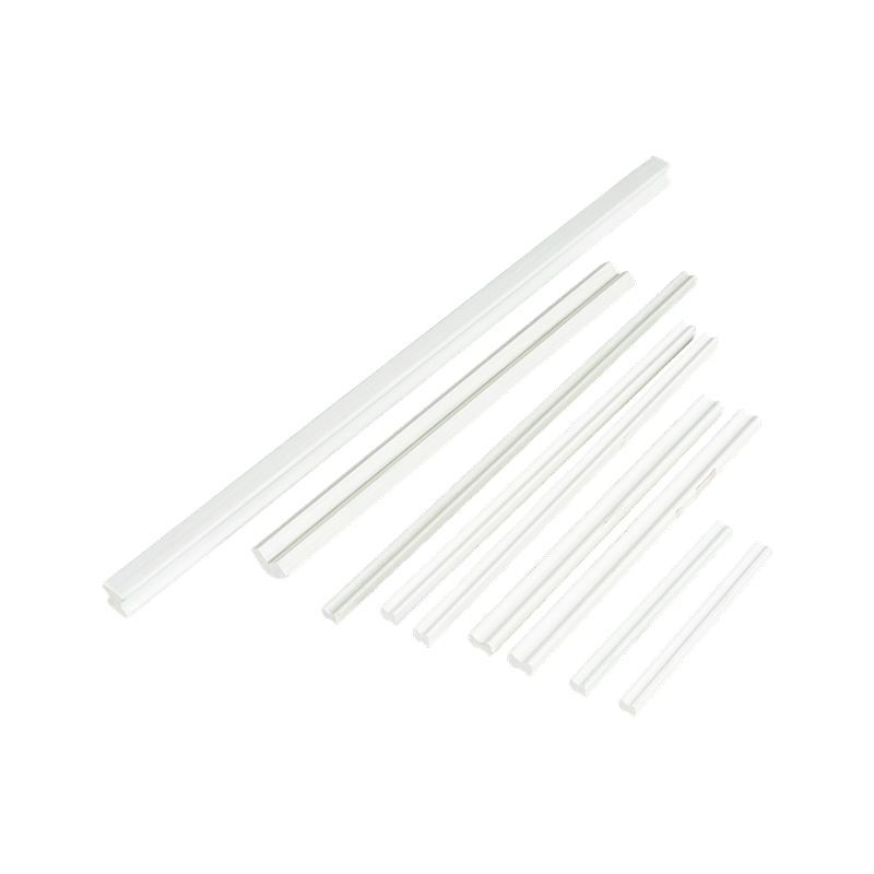
I. Product IntroductionDry-type transformer I-beam support bars, also known as I-beams, traction bars, or ventilation bars, are insulating support profiles integrally formed through a continuous pultr...
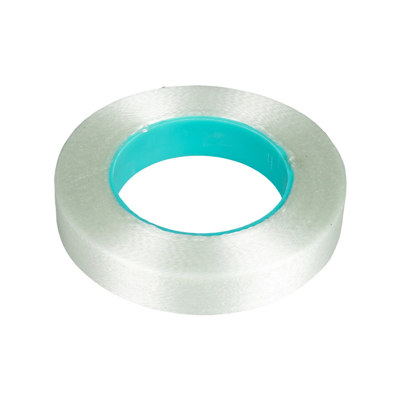
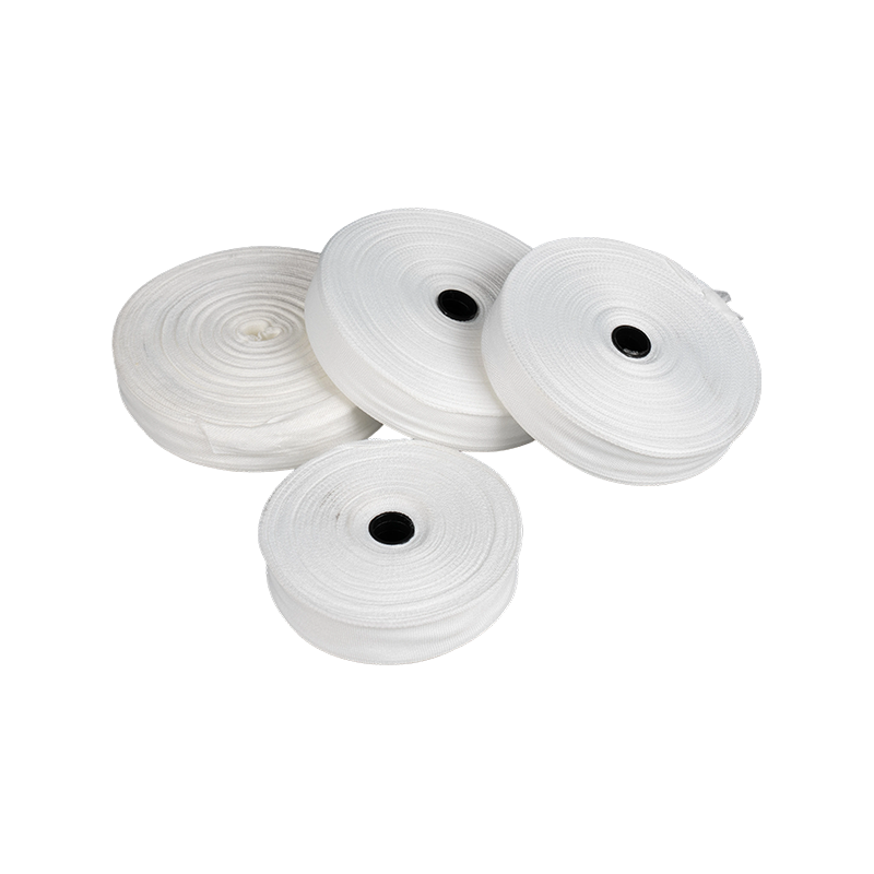
I. Product IntroductionFiberglass non-woven tape is a specialized insulating binding material for motors, transformers, and instrument transformers. Its core consists of unidirectionally arranged cont...
Shrink Tape is a professional heat-shrinkable sealing tape designed to provide robust insulation and protection in harsh environments. Unlike traditional electrical tapes that rely solely on adhesives...
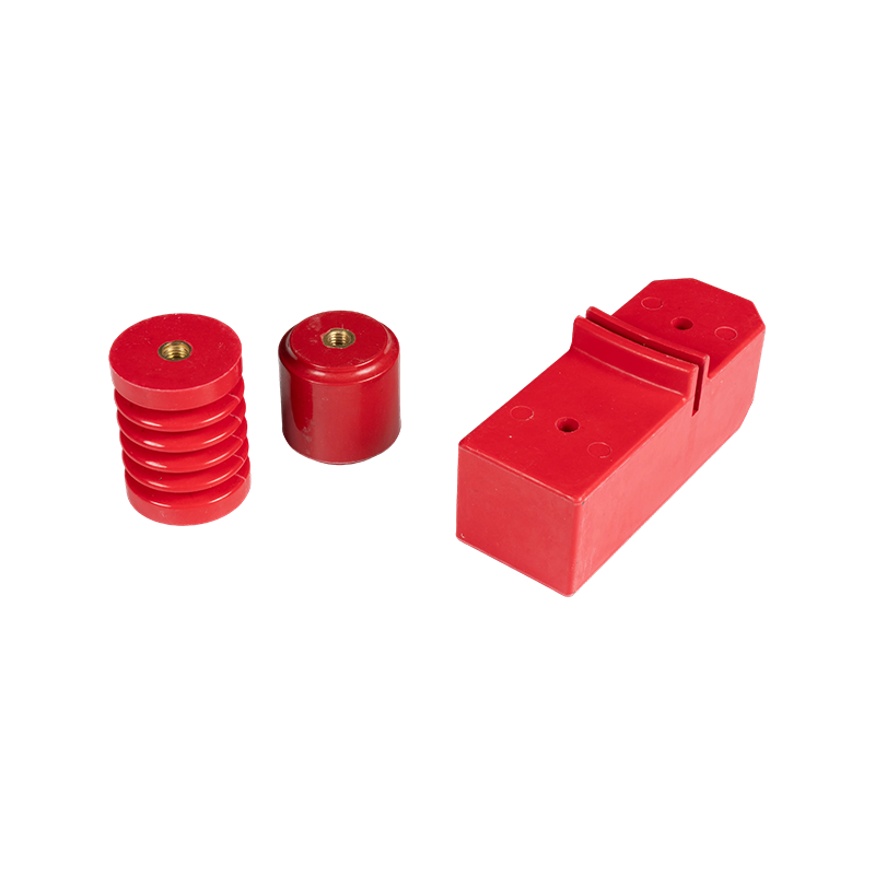
Transformer insulators are insulating support components installed on the transformer body, bushings, and outgoing line devices. Their core function is to achieve electrical isolation and mechanical f...
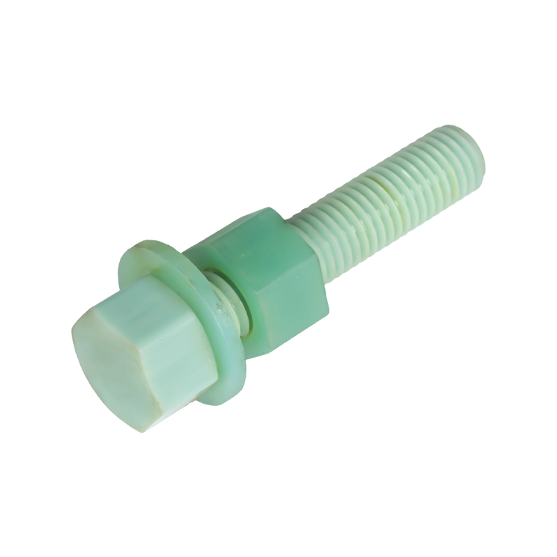
Transformer Fasteners Product IntroductionFiberglass Reinforced Plastic (FRP) transformer fasteners are special insulating fastening components made of fiberglass as the reinforcing material and epoxy...
In the field of building reinforcement and repair materials, GFRP Epoxy Resin Mesh Sheet represents an innovative composite material solution. Compared to traditional metal mesh or alkali-resistant fi...
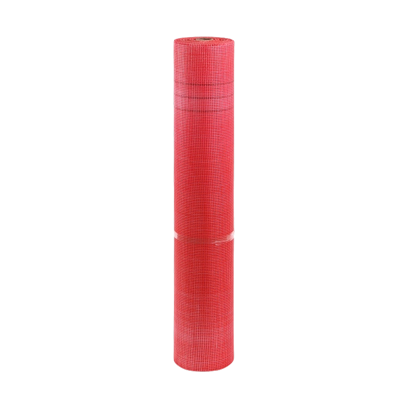
130-160g Outer Wall Fiberglass Mesh Fabric is a reinforcing material specifically designed for building exterior wall insulation systems, acting as a "soft steel reinforcement" within the system. This...
300g Fiberglass Mesh Fabric is a reinforced alkali-resistant fiberglass mesh fabric with a unit area mass of not less than 300 grams per square meter. This product uses medium-alkali or alkali-free wo...

 English
 中文简体
中文简体 Español